What are Texas F-Shape to Low Profile Precast Concrete Traffic Barrier (PCTB) Specifications (Type T)?
The Texas Department of Transportation outlines specifications regarding the proper dimensions for F-Shape to low profile precast concrete traffic barriers (PCTB), Type T, including general notes, section details, and more.
The transition is from CSB (F-Shape) to LPCB (Low Profile).
Texas F-Shape to Low Profile Precast Concrete Traffic Barrier (PCTB) (Type T) General Notes
The Texas Department of Transportation’s general instructions are as follows:
- Concrete should be Class H with a minimum compressive strength of 3,000 psi.
- Where used, rebar reinforcement should be Grade 60 and conform to ASTM A615.
- These details cover barrier per Item 512, “Portable Concrete Traffic Barrier.”
- Precast barrier transition lengths should be 10 feet, unless otherwise specified.
- All precast barrier edges should have a ¾” chamfer or tooled radius.
- All steel assemblies for joint should be galvanized after fabrication in accordance with Item 445, “Galvanizing.”
- Joint connection systems are considered subsidiary.
- For rebars, use 2” bending pin unless otherwise shown.
Texas F-Shape to Low Profile Precast Concrete Traffic Barrier (PCTB) Specifications (Type T)
Texas PCTBs Type T should conform to the following specifications, according to the Texas Department of Transportation.
Plan and Elevation Views
Barrier segments include two 24” lifting slots, a 1” diameter PVC for drainage pipes, and a trough for bolt joint connections. The LPCB bottom measures 26” and the LPCB top measures 28”. The CSB bottom measures 9-1/4” on the top and 24” on the bottom.
The formwork transition lines measure 3” long. On the right end of each barrier, there is a 1-1/2” nominal diameter Sch 40 steel pipe for 1-1/4” diameter connection bolts.
Section A-A
There are two holes running through the center of the barrier. These holes are stacked vertically and spaced 6” apart from each other; the lower hole is spaced 12-3/4” from the bottom of the barrier, and the top hole is spaced 8-3/4” from the top of the barrier.
Barriers measure 24” wide at the bottom and 9-1/2” wide at the top.
Section C-C
Section C-C of the barrier measures 26” at the bottom, 28” at the top, and 20” tall. Barriers are symmetrical in nature.
Detail J for CSB-Side Block-Outs
This section of the barrier includes an upper leave-out and a lower-leave out. The lower leave out measures 11-1/8” long and the upper leave out measures 9-3/8” long.
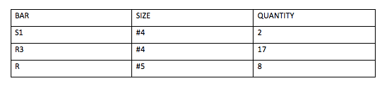
Barrier Transition Elevation Reinforcement Placing
Reinforcement bars are spaced both vertically and horizontally within the barrier. Starting with vertical bars from left to right, the spacing between them is as follows:
- V1 – V2 = 3-1/8”
- V2 – V3 = 13”
- V3 – V4 = 4”
- V4 – V5 = 4”
- Bars V5 to V14 are each spaced 5-1/2” apart from each other
- Bars V14 to V18 are spaced 4-1/2” apart from each other
- V18 – V19 = 4”
- V19 – V20 = 3-1/2”
- V20 – V21 = 3-1/2”
On the left side of the barrier, the horizontal bars are stacked at different intervals. The distance between each horizontal bar and the ground line is as follows:
- L4 = 6-1/4”
- L3 = 9-1/8”
- L2 = 15-5/8”
- L2 = 18-7/8”
- L1 = 28-1/8”
On the right side of the barrier, the horizontal bars are stacked at different intervals. The distance between each horizontal bar and the ground line is as follows, from the lowest H1 to the highest H1: 4-5/8”; 7-1/2”; 12-3/4”; 17-1/4”.
This blog post is an interpretation of specifications by the Texas Department of Transportation (TxDOT). Please consult with TxDOT' most recent requirements for definitive information.

Buy and sell with Eiffel Trading
Eiffel Trading’s online platform markets a large variety of new and used precast barrier wall options, including various DOT specs, low profile barrier, f-shape barrier, and more. In addition, our inventory of marine equipment ranges from sectional barges, to tug boats, to crew boats, and everything in between.
All of our listings are constantly being updated, but if you don’t see what you’re looking for, create a wanted listing for free.
Ready to sell your used heavy equipment or construction material? List your products today for free on Eiffel Trading’s online marketplace.
If you have any questions or would like additional information, please call us at 1-800-541-7998 or email sales@eiffeltrading.com.