Tips & Advice Posts

What are the Wisconsin Temporary Precast Concrete Barrier 12’-6” Specifications?

The State of Wisconsin Department of Transportation outlines specifications regarding the proper dimensions for 12’-6” temporary precast concrete barriers, including general notes, end view specifications, section A-A and B-B details, elevation view specifications and plan view details.

Wisconsin Temporary Precast Concrete Barrier General Notes

  1. Do not intermix concrete barrier temporary precast 12’-6” with other temporary concrete barriers.
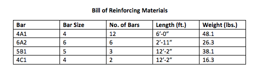
  2. Use ASTM A-615, Grade 60, deformed steel bars for bars 4A1, 6A2, 5B1 and 4C1 in the barrier section; and for 4V1, 4V2, 4V3, 4V4, 4V5, 4V6, 4F1, 4F2 and 5F3 in the barrier taper section.
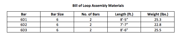
  3. Loop bars 6D1, 6D2 and 6D3 should be ¾” smooth steel bars with a minimum yield strength of 60 KSI, a tensile strength of not less than 1.25 times the yield strength, but a minimum of 80 KSI, a minimum 14% elongation in 8 inches and passing a 180 degree bend test using a 3-1/2” pin bend diameter for bend tests. The loops should be installed within 1/8” of the plan dimension.
  4. Construct lifting slots as specified on the plans to facilitate the drainage of water after installation.
  5. Place barrier on a paved surface. Remove all loose dirt and sand from the roadway surface prior to placing the barrier.
  6. Install mechanical or adhesive anchors per manufacturer’s recommendations. Provide manufacturer’s information to project engineer.
Each barrier should include the following:
  1. Mark one end of each barrier permanently by forming into the barrier the following information:
a. Type: WI CBTPb. Manufacturerc. Date manufactured (month and year)
  1. 1” chamfer to prevent spalling is optional
  2. A 3/8” hole in the connection pin, at the location shown, is acceptable but not required.
  3. “V” notch is optional
  4. The 4” diameter 11 gague steel round mechanical tubing sleeve for lifting is optional
  5. Never use loop bars to lift, move or reposition the barrier
  6. Use delineators conforming to section 633 of the standard specifications. The contractor may use alternate shapes and housing. Install delineators according to manufacturing instructions. Install yellow reflectors when the barrier is located to the left of traffic and white reflectors when the barrier is located to the right of traffic. Space delineators at a maximum of 25 feet apart. Provide top mounted delineators in addition to the side mounted delineators on all barrier installations that are located on a curved alignment longer than 200 feet, as well as on barriers used to separate traffic.

Wisconsin Temporary Precast Concrete Barrier End View Specifications

From an end view, Wisconsin barrier panels should conform to the following:
  • Height: 2”-8”
  • Bottom width: 1’-10-1/2”
  • Top width: 8”
  • Height of the bottom slope: 7”
  • Height of the top slope: 1’-10”
  • Break point: 10” from the pavement or ground line
  • Vertical reveal: 3”
  • Symmetrical in nature
  • 1” chamfer typical
  • An anchor bolt blockout on each side (anchor on traffic side only when required)

Wisconsin Temporary Precast Concrete Barrier Section A-A Specifications

From an end view, Wisconsin barrier panels should conform to the following:
  • Height of anchor bolt inside the panel: 6-1/2”
  • V notch optional
  • Distance between ground line and 2-5B1: 6-1/2”
  • Distance between top of anchor bolt and 2-4C1: 8”
  • Distance between 2-4C1 and 1-5B1: 1’-2-5/8”
  • Distance between 1-5B1 and top of panel: 2-7/8”
  • 1-3/4” minimum CL between side of stirrup and side of panel
  • 1” CL. To 62A bar

Wisconsin Temporary Precast Concrete Barrier Section B-B Specifications

From an end view, Wisconsin barrier panels should conform to the following:
  • V notch length: 7”
  • Distance between ground line and 2-5B1: 6-1/2”
  • Distance between 2-5B1 and 2-4C1: 8”
  • Distance between 2-4C1 and 1-5B1: 1’-2-5/8”
  • Distance between 1-5B1 and top of panel: 2-7/8”
  • 2” minimum CL between top of stirrup and top of panel
  • 1-3/4” minimum CL between side of stirrup and side of panel
  • 62A anchor bolts
  • 1” CL to 6A2 bar

Wisconsin Temporary Precast Concrete Barrier Elevation View Specifications

Wisconsin barriers should conform to the following dimensions and include the following features:
  • Length: 12’-6”
  • 3-3/8” plus or minus 1/8” when measure from face of rail to outside edge of loop bar
  • 6” between ground line and loop bar 6D3 (on the right side)
  • 1’-5” between loop bar 6D3 and 6D2 (on the right side)
  • 3” between loop bar 6D2 and 6D1 (on the right side)
  • 6” between loop bar 6D1 and top of panel (on the right side)
  • 4-1/2” between ground line and loop bar 6D1 (on the left side)
  • 3” between loop bar 6D1 and 6D2 (on the left side)
  • 1’-5” between loop bar 6D2 and 6D3 (on the left side)
  • 7-1/2” between loop bar 6D3 and top of panel (on the left side)
  • An anchor bolt blockout in the center of the panel on both sides
  • Two lifting slots, each 1’-0” long, located 3’-0” from each end of the panel

Wisconsin Temporary Precast Concrete Barrier Plan View Specifications

Wisconsin barriers should conform to the following dimensions and include the following features, according to the plan view:
  • Length: 12’-6”
  • Width: 1”-10-1/2”
  • Three pairs of loop bars, spaced 4’-3” apart from each other, and 2’-0” from the end of the barrier
*Please note that this blog post is an interpretation of Wisconsin Department of Transportation's specifications. Please consult with Wisconsin DOT's most recent requirements for definitive information.

BUY AND SELL WITH EIFFEL TRADING

Eiffel Trading’s online heavy civil marketplace boasts a large variety of used precast barrier wall inventory, including used jersey barrier wall, used k-rail barrier wall, and so much more. Furthermore, our construction equipment listings range from used shoring equipment, to used foundation equipment, and everything in between.All of our listings are constantly being updated, but if you don’t see what you’re looking for, create a wanted listing for free.Ready to sell your used heavy equipment or construction material? List your products today for free on Eiffel Trading’s online marketplace.If you have any questions or would like additional information, please call us at 1-800-541-7998 or email sales@eiffeltrading.com.
Click to continue

What are the Indiana Anchored Temporary Concrete Barrier Drop-In Anchor Specifications?

The Indiana Department of Transportation outlines specifications regarding the proper dimensions for anchored temporary concrete barrier drop-in anchors, including general notes, front view details, end view details, top plate details, bracket details and washer details.

Indiana Concrete Barrier General Notes

  1. All steel should be ASTM A-36 hot rolled unless otherwise noted.
  2. J-J Hooks are a produce of Easi-Set Worldwide. Hooks should be cast into the barrier in accordance with the manufacturer’s recommendations.
  3. The bolt should be installed snug tight in the cast-in ferrule loop insert. The insert should have a minimum ultimate shear capacity of 12.1 kips.
  4. Bent plate anchor bracket should be attached to a concrete surface using one of the following anchor systems. Minimum embedment should be in accordance with the manufacturer's recommendations, but not less than 4 1/2 in.
a. 1-in. threaded rod, grade 55 minimum, with washer and nut. Rod should be installed using an approved epoxy chemical anchor system with a minimum ultimate shear capacity of 21.2 kips: orb. 1-in. diameter wedge anchor; orc. 1-in. nominal diameter drop-in anchor with 1-in. diameter, grade 5 hex bolt.
  1. When concrete will remain in place after anchoring is removed, the threaded rod anchoring system should be used. The rod should be completely removed, the hole should be blown out to remove any moisture or debris, and the hole completely filled using the same epoxy that was used for anchoring the rod.
  2. See E 801-TCCB-05 for bent plate anchor details, top plate washer details, and additional notes.

Indiana Concrete Barrier with Drop-In Anchor Front View Details

Indiana temporary concrete barriers with drop-in anchors should include the following features when viewed from the front:
  • 2 top plate washers (typ.) paired with 2 top plates on each panel
  • 1’-9” between the outer ends of each connecting top plate, when stretched between two panels
  • 5-3/4” (typ.) between the center of each washer and the end of the panel
  • 1” x 1-3/4” Grade 5 hex bolt
  • 1” drop-in anchor in field drilled hole (typ.) (See general note #3)
  • J-J hook (typ.) at the end of each panel
  • 3 bent plate anchor brackets (typ.) spaced 3’-4” apart from each other, and spaced 1’-2” from each end of the panel; there should be 1’-8” of space when measuring from the end of the panel to the center of the first bent plate anchor bracket

Indiana Concrete Barrier with Drop-In Anchor End View Details

Indiana temporary concrete barriers with drop-in anchors should include the following features when viewed from the end:
  • Bottom slope starts 10” from ground line
  • J-J hook located 1’-10” from ground line
  • Each panel should be no less than 1’ from any ground line free edge
  • The top plate washer and top plate should be centered at the top of the panel

Indiana Concrete Barrier with Drop-In Anchor Top Plate Details

Indiana temporary concrete barrier drop-in anchor top plates should conform to the following dimensions:
  • Length: 1’-9”
  • Width: 3-1/2”
  • Distance between slots: 1’-1”
  • Distance between center of slot and short edge of plate: 4”
  • Distance between center of slot and long edge of plate: 1-3/4”
  • Slot detail 1-1/4” x 2-1/2” (typ.)

Indiana Concrete Barrier with Drop-In Anchor Bracket Details

Indiana temporary concrete barrier drop-in anchor brackets should conform to the following dimensions:
  • Length: 11-7/8”
  • Width: 1’-0”
  • PL ½” x 1’1” x 1’-0”
  • PL ½” x 7-1/2” x 1’-0”
  • Lower side angle: 144 degrees
  • Upper side angle: 148 degrees
  • Top side length: 2-7/8”
  • Bottom side length: 5-1/2”
  • 1-1/8” hole

Indiana Concrete Barrier with Drop-In Anchor Top Plate Washer Details

Indiana temporary concrete barrier drop-in anchor washers should conform to the following dimensions:
  • 4” x 4” square
  • 1-1/16” diameter hole centered in the plate
  • PL ¼” x 4” x 4”
*Please note that this blog post is an interpretation of Indiana Department of Transportation's specifications. Please consult with Indiana DOT's most recent requirements for definitive information.

BUY AND SELL WITH EIFFEL TRADING

Eiffel Trading’s online marketplace hosts a wide variety of used barrier wall, including used single slope barrier wall, used f-shape barrier wall, used jersey barrier wall, and much more. Additionally, our construction material inventory ranges from used sheet pile, to used access trestle, and everything in between.All of our listings are constantly being updated, but if you don’t see what you’re looking for, create a wanted listing for free.Ready to sell your used heavy equipment or construction material? List your products today for free on Eiffel Trading’s online marketplace.If you have any questions or would like additional information, please call us at 1-800-541-7998 or email sales@eiffeltrading.com.
Click to continue

What are the West Virginia DOT Jersey Barrier Specifications?

The West Virginia Department of Transportation outlines specifications regarding the proper dimensions of six inch Jersey shape concrete barrier walls, including general notes, end view specifications, plan view specifications, elevation details, connector details and plate details.

West Virginia Jersey Barrier General Notes and Specifications

Jersey barriers in West Virginia must conform to the following specifications:Materials
  1. Concrete: Class AA concrete 5,000 PSI minimum compressive strength
  2. Reinforcing: ASTM A-708 Grade 80; rebars welded to steel connector plates; ASTM A-185 welded wire fabric
  3. Steel: ASTM A-36
Tolerance
  1. Connector location plus or minus 1/16”
  2. Width of connector plus or minus 1/32”
  3. Connector plate size + 1/8”
  4. Barrier length + ¼”
WeldingAll welding should be in accordance with American Welding Society structural welding codesDesignFHWA approved shape. J-J hooks should be accepted by FHWA as a crash tested and operational design for use on all federal highway projects.InstallationBarriers should be installed at maximum separation in order to minimize barrier deflection upon impact.There is a maximum separation of 1-1/2”.

West Virginia Jersey Barrier End View Specifications

From an end view, West Virginia Jersey barriers should conform to the following:
  • Bottom width: 2’-0”
  • Top width: 8”
  • Height of the bottom slope: 1”-1”
  • Height of the top slope: 10”
  • Break point: 10” from the pavement or ground line
  • Vertical reveal: 3”

West Virginia Jersey Barrier Plan View Specifications

Each Jersey barrier panel in West Virginia should conform to the following dimensions and include the following features:
  • Width: 2’-0”
  • Length: 12’-0”
  • ¾” chamfer at each end
  • 3/8” plastic insert with NC thread
  • Rebar and mesh running through the center of each panel

West Virginia Jersey Barrier Elevation Details

Each Jersey barrier panel in West Virginia should conform to the following dimensions and include the following features:
  • Height: 2’-8”
  • Length: 12’-0”
  • One drainage slot located at the center of the panel
  • 6 x 6 mesh that is 1’-6” wide
  • ASTM A-708 bars welded to each end connector
  • 1’-0” space between the welded bars
  • 10” between each end of the connector plate and the ends of the panel
  • The end of the barrier should be sloped back from the top of the connector to top of the barrier, with ½” of space created through the slope
  • 3/8” plastic insert with NC thread
  • Rebar and mesh running through the center of each panel

West Virginia Jersey Barrier Positive Connector and Connector Plate Details

Positive connectors and connector plates should conform to the following dimensions and include the following features:Positive Connectors
  • Two interlocking connector plates
  • 2 x 2 x 3/18 angle
  • ASTM A-708 grade 80 bars

Connector Plates

  • 3/8” connector plate thickness
  • ¾” between the center of the connector plate hook and the top of the plate
  • ASTM A-708 grade 80 bars
*Please note that this blog post is an interpretation of West Virginia Department of Transportation's specifications. Please consult with WV DOT's most recent requirements for definitive information.

BUY AND SELL WITH EIFFEL TRADING

Between used jersey barrier wall, used k-rail barrier wall, used f-shape barrier wall, and more, Eiffel Trading’s online marketplace has it all! In addition, our construction equipment inventory includes used foundation equipment, used cranes, and much more.All of our listings are constantly being updated, but if you don’t see what you’re looking for, create a wanted listing for free.Ready to sell your used heavy equipment or construction material? List your products today for free on Eiffel Trading’s online marketplace.If you have any questions or would like additional information, please call us at 1-800-541-7998 or email sales@eiffeltrading.com.
Click to continue

Eiffel 101: Barge Safety Checklist

Barges are indispensable in many industries for storage and transportation of equipment and materials and for use as work platforms on water. Barge accidents involving injury to crew members and damage to property are not uncommon, but they can be prevented in many cases with the correct safety protocols in place. The United States Coast Guard (USCB) has some particular suggestions for maintaining safety on barges. Below are some recommendations based on their safety advice for those working on barges:

INSPECTIONS

  • If they don't have current ABS classification, barges should be thoroughly inspected annually by a USCG official or an experienced marine surveyor with accreditation from the Society of Accredited Marine Surveyors (SAMS) or National Association of Marine Surveyors (NAMS).
  • Annual inspections should, minimally, assess overall structural conditions of a barge. Beyond this, they should also be specific to the particular type of barge, i.e. spud barge, deck barge, sectional barge, etc. and specific to the particular type of equipment used on the barge.
  • All equipment used on a barge should be inspected on a regular basis as recommended by the equipment’s manufacturer.
  • All materials should be stored securely at all times, and barges should be inspected on a regular basis to ensure that materials are in their proper places.
  • Results of inspections should be carefully documented, and inspection reports should be stored in an established location onboard a barge for crew members to reference if needed.
  • If a barge is deemed unsafe or not in proper working order during an inspection, it should be taken out of commission and not used until all safety issues are properly addressed and all necessary repairs are made.
  • If any equipment on a barge is deemed unsafe or in need of repair, it should be promptly removed from the barge until it passes further inspections.
  • Before a barge is filled or emptied, it should be inspected for leaks.

PREPAREDNESS

  • Barge decks should be organized well, and all equipment and materials not in use should be stored properly.
  • Employees should be informed of where all safety equipment is on the barge. Safety equipment stock checks should be performed regularly to ensure that all necessary equipment is available to crew members. If safety equipment is damaged, it should promptly be replaced with new equipment.
  • Employees should be well-aware of the locations of all openings and hatches on deck.
  • A disaster preparedness plan should be in place so there is a protocol to minimize harm to workers and property in the event of a hurricane, tropical storm, flood, or other weather event.
  • As a part of disaster preparedness, employees should be well aware of the conditions in which a barge must be relocated to a more protected area based on tide/river gauge readings. If a barge is not self-propelled, a plan should be in place to move it using a self-propelled vessel like a tug boat or pull boat.
  • If a barge is not self-propelled, it’s a good idea to always have a pull boat, tug boat, or similar boat in the area should the barge have to suddenly be relocated.
  • All crew members should complete required safety trainings on a regular basis that cover both barge safety and safety regarding the specific duties of their positions.
As we mentioned, there are some safety concerns that are specific to the type of barge or the type of equipment being used. This list doesn’t cover all the bases of barge safety, but it covers many of the important ones. Remember that an ounce of prevention is worth a pound of cure in terms of keeping workers safe and that training and inspections can ultimately save you a lot of trouble.

BUY AND SELL WITH EIFFEL TRADING

Eiffel Trading’s online marketplace hosts a wide variety of used barges, including but not limited to deck barges, accommodation barges, sectional barges, and much more. Additionally, our construction material inventory ranges from used sheet pile, to used HDPE pipe, and everything in between.All of our listings are constantly being updated, but if you don’t see what you’re looking for, create a wanted listing for free.Ready to sell your used heavy equipment or construction material? List your products today for free on Eiffel Trading’s online marketplace.If you have any questions or would like additional information, please call us at 1-800-541-7998 or email sales@eiffeltrading.com.
Click to continue

How is a Seawall Constructed?

A seawall is a protective structure or embankment used in a coastal area to help mitigate damage and disturbance associated with waves, tides, tsunamis, hurricanes, and other natural disasters. Sea walls protect from overtopping waves and storm surges. They help coastal areas retain soil that would otherwise be lost or disturbed over time, ultimately preventing land from sliding. And they keep real estate and commercial properties as well as other coastal resources safe from water damage.

SEAWALL VS. BULKHEAD

You may have heard of seawalls referred to as bulkheads and vice versa, but true sea walls differ from true bulkheads in that they provide shelter from waves as well as retaining soil in an area. A bulkhead, on the other hand, primarily serves the purpose of providing stabilization at the shoreline in order to retain soil. Both seawalls and bulkheads help stop the land from sliding due to their soil retention capabilities, but seawalls are bigger and serve the dual purpose of interrupting waves and surges. Seawalls are frequently constructed using concrete, while bulkheads may be constructed using gravity structures or sheet piling.

MATERIALS

As mentioned, seawalls can be made of concrete, but they are also quite often made of steel. Many are made of concrete with steel reinforcements. They can also be constructed of timber, boulders, vinyl, or composites. Vinyl seawalls are a popular option when a seawall needs to be constructed easily and quickly, but they need to be replaced every 20 years or so. Wooden seawalls are an attractive choice, but they are the most easily damaged of all types. When seawalls are constructed, they can have seaward faces that are concave, vertical, or stepped. They are commonly built with defensive materials referred to as revetments, which are laid on their slopes. Additionally, they may include quays and landing platforms for unloading and loading vessels. They may also be engineered with jetties, groins, and offshore breakwater.

STEEL AND VINYL SHEET PILE

When constructed with steel, seawalls are often comprised steel sheet pile. Steel sheet pile is a great option for seawall construction because of their relative ease of installation, strength, and longevity. Although they can acquire damage and erosion from years of saltwater wear and tear, steel sheet pile is relatively long-lasting. Additionally, when steel sheet piles are not utilized, vinyl sheet piles are a great alternative. While vinyl sheet piles do not carry the same strength as steel sheet piles, vinyl sheets are less susceptible to corrosion than steel.Engineering specs will differ based on the requirements of the particular area where a seawall is installed. Soil properties, topography conditions such as grading and elevation, embedment, and water levels should all be carefully assessed during the design process to ensure a high-quality build. Zoning restrictions as well as local ordinances must be considered in the construction process.The frequency and scope of maintenance and repair after a seawall is constructed will differ based on the materials used in construction as well as coastal conditions, i.e. how many storms occur in a particular area at any given time. Seawalls that are failing can pose significant risk to coastal properties and other resources. Seawalls that do not adequately do their jobs may have erosion holes, settling soil, or long cracks that present issues. These vulnerabilities should be promptly addressed through repair or replacement of damaged seawalls.

EQUIPMENT

Types of equipment used in seawall construction include excavators to prepare an area for installation and for backfilling, pile driving equipment if piles are to be installed, barges for storage of equipment and materials, cranes, tiebacks, anchors, welding equipment, and other specialized equipment, depending on the particular seawall construction project.In some areas where construction of a new seawall is being proposed, the pros and cons of construction must be carefully weighed. Seawalls do a lot of good, but they can also harden shorelines on coastal ecosystems and can otherwise disrupt the natural coastal exchange of sediment. This can result in damage to intertidal beaches and wetlands. Sea walls can also contribute to the dissipation of beaches due to how they modify the transport of sediments. If the need to protect an area from natural disasters and erosion is critical, though, a sea wall is a very viable choice.

BUY AND SELL WITH EIFFEL TRADING

Eiffel Trading’s online marketplace hosts a wide variety of used construction material and equipment. Our inventory ranges from used sheet pile, to to used barges, to used foundation equipment, and everything in between. In addition, we recently launched an aggregate and soil section, to connect buyers and sellers.All of our listings are constantly being updated, but if you don’t see what you’re looking for, create a wanted listing for free.Ready to sell your used heavy equipment or construction material? List your products today for free on Eiffel Trading’s online marketplace.If you have any questions or would like additional information, please call us at 1-800-541-7998 or email sales@eiffeltrading.com.
Click to continue

What are the Rhode Island DOT Unanchored Precast Concrete Barrier Specifications?

The Rhode Island Department of Transportation outlines specifications regarding the proper dimensions of unanchored precast concrete barriers for temporary traffic control, including general notes, barrier plan designs, section A-A specifications, section B-B specifications, section C-C specifications, and elevation details.*Please note that this blog post is an interpretation of Rhode Island Department of Transportation's specifications. Please consult with Rhode Island DOT's most recent requirements for definitive information.

Rhode Island Barrier General Notes

  1. Barriers should be in accordance with section 926 of the Rhode Island standard specifications.
  2. Bend rebars around a 1-3/8” pin
  3. R-1 bars should be fabricated continuously.
  4. R-2 bars should be fabricated with 2’-0” minimum laps as shown on the detail.

Rhode Island Concrete Barrier Plan Design

Unanchored precast concrete barriers in Rhode Island should include the following:
  • Two 2” lifting holes set 1’-6” from each end of each panel
  • A 3” open joint between each panel
  • Each panel should be 2’-0” wide and 10’-0” long

Rhode Island Concrete Barrier Section A-A

From an end view, section A-A panels should conform to the following:
  • Height: 2”-9”
  • Bottom width: 2’-0”
  • Top width: 6”
  • Bottom slope starts 4” from ground line
  • Height of the bottom slope: 10”
  • Height of the top slope: 1’-7”
  • Break point: 14” from the pavement or ground line
  • Vertical reveal: 4”
  • Symmetrical in nature

Rhode Island Concrete Barrier Section B-B

From an end view, section B-B panels should conform to the following:
  • Distance between R-1 and R-2: 1’-9”
  • ½” chamfer (TYP. Both ends)
  • 1” shear pin at the top
  • Symmetrical in nature

Rhode Island Concrete Barrier Section C-C

From an end view, section C-C panels should conform to the following:
  • Distance between R-1 and R-2: 1’-9”
  • Distance between R-1 and the top of the panel: 7”
  • ½” chamfer (TYP. Both ends)
  • 1” shear pin at the top
  • Symmetrical in nature

Rhode Island Concrete Barrier Elevation Detail

From a side view, Rhode Island unanchored precast concrete barriers should conform to the following dimensions:
  • Length: 10’-0”
  • Height: 2”-4”
  • Bar R-1 and #5 Bar R-2 should be inserted through the panel on an incline
  • Distance between #5 Bar R-1 and the top of the panel on the left: 5”
  • Distance between #5 Bar R-1 and the top of the panel on the right: 7”
  • Distance between #5 Bar R-1 and #5 Bar R-2: 1’-9”

BUY AND SELL WITH EIFFEL TRADING

Eiffel Trading’s online marketplace hosts a wide variety of new and used temporary precast barrier wall options, including but not limited to k-rail, f-shape, jersey barrier, and much more. Furthermore, our inventory of construction material ranges from used wide flange beams, to used HDPE pipe, and everything in between.All of our listings are constantly being updated, but if you don’t see what you’re looking for, create a wanted listing for free.Ready to sell your used heavy equipment or construction material? List your products today for free on Eiffel Trading’s online marketplace.If you have any questions or would like additional information, please call us at 1-800-541-7998 or email sales@eiffeltrading.com.
Click to continue

What are Minnesota Temporary Portable Precast Concrete Barrier Type “F” Specifications?

The Minnesota Department of Transportation outlines specifications regarding the proper dimensions for temporary portable precast concrete barrier type “F,” including elevation views, plan views, end views, and more.Minnesota Temporary Portable Precast Concrete Barrier General Notes
  1. This barrier should be consistent with type SWC09, as defined in “A Guide to Standardized Highway Barrier Hardware.”
  2. Barrier sections should not be permanently incorporated into construction or maintenance projects.
  3. At no time should the barrier be lifted or moved by the use of the loop bars 6D1, 6D2 or 6D3.
Definitions are as follows:
  1. Marked end: the marked end is the end of the barrier that has one loop bar at the top and two loop bars at the bottom. Each barrier should be permanently marked on this end with the following information:
a. Type 8337Cb. Name or trademark of manufacturerc. Location of plantd. Month and date manufactured
  1. Lifting hole: 4-inch diameter, 11-gague steel round mechanical subbing sleeve. These holes are optional.
  2. V notch is optional.

Minnesota Temporary Portable Precast Concrete Barrier Elevation View Specifications

Each F-barrier panel in Minnesota should conform to the following dimensions and include the following features:
  • Length: 12’-6”
  • Height: 2’-8”
  • Two lifting slots; each slot 1’-0” long, 4-1/2” high; each slot beginning 4’-3” from each outside end of the panel
  • Two lifting holes; the center of each hole should be located 2’-1-1/2” from each outside end of the panel, and 1’-0” from the bottom of the panel
  • One anchor blockout located at the bottom center of the panel on both sides
  • 3-3/8” plus or minus 1/8” measured from the face of the barrier to the outside edge of the loop bar

Minnesota Temporary Portable Precast Concrete Barrier Plan View Specifications

Each F-barrier panel in Minnesota should conform to the following dimensions:
  • Width: 1’-10-1/2”
  • Length: 12’-6”
  • Distance between the end of the panel and the first set of lifting holes: 2’-0”
  • Distance between the first set of lifting hole and the center set of lifting holes: 4’-3”
  • Diameter of each lifting hole: 2”
  • Distance between the long edge of the panel and the center of each lifting hole: 3”

Minnesota Temporary Portable Precast Concrete Barrier End View Specifications

From an end view, Minnesota panels should conform to the following:
  • Height: 2”-8”
  • Bottom width: 1’-10-1/2”
  • Top width: 8”
  • Height of the bottom slope: 7”
  • Height of the top slope: 1’-10”
  • Break point: 11” from the pavement or ground line
  • Vertical reveal: 4”
  • V notch length: 7”
  • Symmetrical in nature
  • ¾” chamfer typical

Minnesota Temporary Portable Precast Concrete Barrier Tables

Minnesota Temporary Portable Precast Concrete Barrier Loop Bar Specifications

Minnesota loop bars used for temporary portable precast concrete barrier type F should conform to the following:
  • Length of each bar: 2’-10-1/2”
  • Height of each bar: 1’-4”
  • Diameter: 9”
  • Width: 4-1/4”
  • Hairpin curve diameter: 2-3/4”
  • Order of bar assembly, from top to bottom: 6D3, 6D2, 6D1

Minnesota Temporary Portable Precast Concrete Barrier Vertical Stirrup Bar 4A1 Specifications

Minnesota vertical stirrup bars 4A1 used for temporary portable precast concrete barrier type F should conform to the following:
  • Height: 2’-4-1/4”
  • Bottom length: 1’-3”
  • Upper interior curve diameter: 4-1/4”
  • Lower interior curve diameter: 2-1/2”
  • Lower exterior curve diameter: 2” minimum

Minnesota Temporary Portable Precast Concrete Barrier Bar 62A Specifications

Minnesota bars 62A used for temporary portable precast concrete barrier type F should conform to the following:• Interior curve diameter: 6-1/2”• Length: 1’-4-3/8”• Height: 8”

Minnesota Temporary Portable Precast Concrete Barrier Top Plate, Retainer Bolt and Nut, and Connection Pin Details

Top PlatesMinnesota barrier top plates should conform to the following dimensions:
  • Length: 4”
  • Width: 2-1/2”
  • Hole centered on the plate: 1-3/8” diameter
Retainer Bolts and NutsMinnesota barrier retainer bolts and nuts should include a ½” diameter x 10” long grade 8 hex bolt and nut, plus a connection pin.Connection PinsMinnesota barrier connection pins should conform to the following dimensions and include the following features:
  • 5/8” diameter hole for retainer bolt at the bottom of the pin
  • Pin made of 1-1/4” diameter ASTM A36 steel
  • Top plate made of ASTM A36 steel that is ½” thick
  • The pin should be 28” long
This blog post is an interpretation of specifications by the Minnesota Department of Transportation. Please consult with Minnesota's most recent requirements for definitive information.

BUY AND SELL WITH EIFFEL TRADING

Eiffel Trading’s online marketplace hosts a wide variety of new and used temporary precast barrier wall options, including but not limited to k-rail, f-shape, jersey barrier, and much more. Furthermore, our inventory of construction material ranges from used h pile beams, to used steel pipe, and everything in between.All of our listings are constantly being updated, but if you don’t see what you’re looking for, create a wanted listing for free.Ready to sell your used heavy equipment or construction material? List your products today for free on Eiffel Trading’s online marketplace.If you have any questions or would like additional information, please call us at 1-800-541-7998 or email sales@eiffeltrading.com.
Click to continue

What are the Indiana Anchored Temporary Concrete Barrier Specifications?

The Indiana Department of Transportation outlines specifications regarding the proper dimensions for anchored temporary concrete barriers, including general notes, top view details, front view details, connection details and end view details.

Indiana Anchored Temporary Concrete Barrier Specifications General Notes

  1. The dimensions of the lifting slots are subject to adjustment as necessary to accommodate handling equipment.
  2. Maximum barrier taper rate flares for lane closures for legal posted speed are shown in Table No. 1 (below).
  3. For additional connection details see Standard Drawing E 801-TCCB-0.
  4. Where site conditions prohibit the use of these flare rates then flare rates may range from 10:1 to 6:1.
  5. Section A-A shows reinforcement with welded wire fabric. The WWF may be bent to the shape of the wall.
  6. Hex nut may be tack welded to bottom spacer to facilitate installation and removal. Bolts should be torqued only to tight condition. Clearance between the spacer and the ends of the barrier should allow angular deflection at the joints to allow flare rate 11:1 or flatter.
  7. Top spacer TS should be 4" x 2" x 5/16" x 10" long.
  8. Bottom spacer TS should be 4" x 2" x 5/16" x 1'-4" long.
  9. Where necessary to meet short radius curving alignment, the shorter top spacer (10") may be substituted for the standard bottom spacer (16").
  10. Where very short radius curving alignment is encountered, spacers may be TS 3" x 2" x 1/4" x the appropriate length as shown above.
  11. In lieu of the connection detail shown, the J-J Hook temporary barrier connection of Easi-Set Industries as described in FHWA acceptance letter B-52 of March 26, 1999 may be used.
Indiana Anchored Temporary Concrete Barrier Top View DetailsFrom a top view, panels should include:• ¾” threaded inserts• ¾” smooth bar hooks• Typical or optional end treatments• A width of 2’-0”• 3-3/4” between the end of the typical end treatment and the side of the barrier• Smooth bar hooks that are ¾” x 11’-8”

Indiana Anchored Temporary Concrete Barrier Front View Details

Indiana anchored temporary concrete barriers should conform to the following dimensions when viewed from the front:
  • Length: 10’-0”
  • Height: 2’-7”
  • Two lifting holes at the bottom of each panel, set 3’-1/2” from each end of the barrier
  • ¾” threaded inserts
  • Two parallel bars inserted through the panel on an incline
  • Distance between upper bar and the top of the panel on the left: 6”
  • Distance between upper bar and the top of the panel on the right: 7-1/2”
  • Distance between lower bar and the bottom of the panel on the left: 7-1/2”
  • Distance between lower bar and the bottom of the panel on the right: 6”

Indiana Anchored Temporary Concrete Barrier Front View Connection Details

Indiana anchored temporary concrete barrier panels should connect using the following specifications:
  • No more than 4-1/2” between panels
  • Two spacers should be used to connect the panel bolts together
  • Spacers should be 2” high and 4” wide. (See general notes for spacer length details).
  • Spacers should include a 1-1/2” drilled hole in the center of the spacer.
  • Each connector bolt should be 1-1/4” x 2’-2” with a 4” minimum, and should include a threat and hex head, plus two flat washers and a hex nut
  • The smooth bar hooks should be ¾”

Indiana Anchored Temporary Concrete Barrier End View Details

From an end view, panels should conform to the following dimensions:
  • Height: 2”-7”
  • Bottom width: 2’-0”
  • Top width: 10”
  • Bottom slope starts 9” from ground line
  • Height of the bottom slope: 7”
  • Height of the top slope: 1’-10”
  • Break point: 9” from the pavement or ground line
  • Vertical reveal: 2”
  • Symmetrical in nature
  • ½” bevel

Indiana Anchored Temporary Concrete Barrier Table No. 1

This blog post is an interpretation of specifications by the Indiana Department of Transportation. Please consult with Indiana DOT's most recent requirements for definitive information.

BUY AND SELL WITH EIFFEL TRADING

Eiffel Trading’s online marketplace hosts a wide variety of new and used temporary precast barrier wall options, including but not limited to k-rail, f-shape, jersey barrier, and much more. Furthermore, our inventory of construction material ranges from used sheet pile, to used crane mats, and everything in between.All of our listings are constantly being updated, but if you don’t see what you’re looking for, create a wanted listing for free.Ready to sell your used heavy equipment or construction material? List your products today for free on Eiffel Trading’s online marketplace.If you have any questions or would like additional information, please call us at 1-800-541-7998 or email sales@eiffeltrading.com.
Click to continue

Which Materials and Equipment are Used in Marine Pile Driving?

In marine construction, the creation of deep foundations is often necessary to ensure that structures are properly supported. This is especially the case in areas where the surface level of the floor of a lake or an ocean isn’t strong enough to provide support to heavy loads. Pile driving is used as a way to engineer a deep foundation. Piles are driven several feet below the surface of the floor or ground to help create rock-like, sturdy platforms.Sheet piles are often made of steel, concrete, or timber. Composite sheet piles are made of a mixture of concrete and steel. This type of pile can be used to create capped columns or to build wall-like foundations underground. Sheet piles either have to be forcefully driven into the ground, or they are driven into holes that are drilled prior to their placement. The depth of a foundation created using the driving of sheet piles is determined by how far below it takes to reach stable, solid ground.In addition to sheet piling, structural pipe piling is often used in areas of marine construction. Pipe piling creates a tremendous amount of frictional load resistance in deep foundations and boasts excellent point bearing capabilities.

Materials Used in Pile Driving for Marine Construction

  • Sheet pile (steel, concrete, timber, composite, or other types)
  • Steel beams
  • Pipe piles
  • H-piles*
  • Wide flange beams
*An H-pile differs from a wide flange beam because its flanges are as deep as they are wide, and its flange and its web have the same amount of thickness. It’s made up of three connected square components that form the shape of an “H.” This “H” design offers added weight distribution and ultimately greater support for many bigger and weightier structures. H-piles are very useful in dense soils and in rocky areas.

Equipment Used in Pile Driving for Marine Construction

  • Piling hammers (hydraulic hammers, drop hammers, air/steam hammers, diesel hammers, etc.)
  • Piling winches, which are hand-controlled, high-speed winches that help hoist piles up and down
  • Piling rigs mounted on pontoons or barges
  • Hanging leaders (hanged from the jib of a crane)
  • Deck, sectional, or similar functioning barges for safe use of piling equipment
As mentioned, pile driving plays an important role in marine construction, especially in areas like bridge construction and cofferdam construction. Below is some information about how pile driving contributes in these arenas:

Bridge Construction

For bridge construction, pile driving is employed where scour protection is needed or where other foundation materials won’t provide adequate support for direct bearing footings. Steel beams (h-piles and wide flange beams) or concrete sheet piles are common in the building of bridges. The type of hammer used to drive piles for bridge applications is most often one with the heaviest amount of ram that can be applied without damage to the pile itself. Hydraulic, air/steam, gravity, and diesel hammers are common.

Building Cofferdams

A cofferdam is a temporary enclosure built within a body of water that allows water to be pumped out of the area to create a dry surface on which to build. Pile driving is instrumental in the creation of cofferdams. Typically, sheet piles and pipe piles are driven during the construction of a cofferdam. Sheet piles, along with a steel bracing system, help create the overall structure of the cofferdam. Pipe piles are essential to the successful construction of a cofferdam’s foundation, and they are ordinarily driven using hydraulic hammers or diesel hammers, unless another type of hammer is better suited to the project.In addition to being useful in cofferdam and bridge construction, pile driving is also widely employed in the construction of marinas, harbors, quay walls, bulkheads, and wharfs. Wherever a stronger foundation is needed, pile driving can be of service.

BUY AND SELL WITH EIFFEL TRADING

Eiffel Trading’s online marketplace hosts a large variety of both pile driving materials and pile driving equipment. Our pile driving material inventory ranges from wide flange beams, to h pile, to sheet pile, and everything in between. In addition, our pile driving equipment inventory include pile drivers, pile drivers, and much more.All of our listings are constantly being updated, but if you don’t see what you’re looking for, create a wanted listing for free.Ready to sell your used heavy equipment or construction material? List your products today for free on Eiffel Trading’s online marketplace.If you have any questions or would like additional information, please call us at 1-800-541-7998 or email sales@eiffeltrading.com.
Click to continue

What are the Differences Between Inland and Ocean Push Boats?

A push boat, sometimes called a “pusher” or “pusher boat,” is a type of boat engineered for pushing large vessels like barges as well as oil rigs. As opposed to a tug boat, a push boat only pushes, while a tug boat pulls a larger vessel to get it from point A to point B. While push boats are typically used in inland areas, they are also sometimes used in ocean areas. Below is some information about what differentiates inland push boats from ocean push boats.

Inland Push Boats

These are by far the most common kind of push boats. They are employed in river areas, canals, and other inland waterways. Inland push boats typically have a shallow draft, square bow, large plates mounted to their bow to aid in pushing, and knees. They also have flat sterns that help boost their pushing capabilities. Their horsepower output ranges from between around 600 hp to 10,000 hp, with most inland push boats clocking in with horsepower around 1,200 hp. In terms of size, most push boats are between 30 to 250 feet in length and 20 to 60 feet wide. Some larger inland tug boats designed for long hauls offer living quarters and work space for crew members.

Ocean Push Boats

It’s more rare for a push boat to be “ocean-going,” meaning that it is used to haul barges long distances across turbulent ocean waters. This type of task is best handled by an ocean-going tug boat. If you hear a boat referred to as an ocean push boat, it is most likely either meant for use in ocean harbors or for use in coastal or intracoastal waterways. Ocean push boats can perform varied jobs in port, harbor, and coastal areas. Push boats used in harbor areas may be a bit smaller than push boats used in other areas to allow for easier maneuvering. If a push boat is used in the ocean, its exterior is usually treated in a manner that helps prevent corrosion from salt water.Ocean Push Boats vs. Tug BoatsSome push boats are used in offshore construction to move barges and other vessels limited distances or to aid in maneuvering them to meet project needs. As mentioned, tug boats are a better fit for jobs that require moves of extensive distance on the open sea. Ocean-going tug boats are larger in size than push boats and offer more horsepower generally. They are specifically engineered for extensive use in the ocean and to handle turbulence on the water. They often make use of large propellers to increase their towing capabilities. Additionally, they have longitudinal bulkheads, welded-steel hulls, and high lift rudders to enhance their long-distance towing capabilities.

SIMILARITIES

In many ways, there are more similarities than differences between inland push boats and ocean push boats. They both perform similar jobs, and oftentimes a push boat that has been used in inland areas can later be used in ocean areas and vice versa. Many newer push boats, whether inland or ocean, may be truckable too, which means that they can be transported on the road as well as on the water to get them to your project more efficiently. Before you invest in any particular kind of push boat, make sure you know enough about its specs to give you peace of mind that it will be able to handle your towing jobs. If you are buying a used push boat, make sure you also are aware of its history, including any major repairs as well as where and how it’s been used.

BUY AND SELL WITH EIFFEL TRADING

Eiffel Trading’s online marketplace hosts both inland push boats and ocean push boats, in addition to used sectional barges, used deck barges, and much more. Furthermore, our material inventory ranges from brand new steel plates to used precast barrier wall and everything in between.All of our listings are constantly being updated, but if you don’t see what you’re looking for, create a wanted listing for free.Ready to sell your used heavy equipment or construction material? List your products today for free on Eiffel Trading’s online marketplace.If you have any questions or would like additional information, please call us at 1-800-541-7998 or email sales@eiffeltrading.com.
Click to continue
Previous page Next page

© 2025 Eiffel Trading, LLC. All Rights Reserved. Terms of Services / Privacy Policy