Tips & Advice Posts

What are Oklahoma Concrete Longitudinal Barrier Specifications?

The Oklahoma Department of Transportation outlines specifications regarding the proper dimensions for concrete barriers, including general notes, section details, and more.

Oklahoma Concrete Longitudinal Barrier General Notes

The Oklahoma Department of Transportation’s general instructions are as follows:
  1. All construction and material requirements should be in accordance with the 2009 ODOT Standard Specifications.
  2. Price bids should include payment for materials, labor, pipe sleeves, expansion joints, and all incidentals necessary to complete the installation.
  3. For details of longitudinal barrier mounted light pole bases and installations, see the current version of Traffic Standard BMFI-2.
  4. Longitudinal barriers should be measured for payment as continuous barriers. Payment for light pole footings are to be included in other items of work.
  5. When longitudinal barriers are placed on flexible bases or surfacing, contraction joints or chamfers are required at a maximum of 20 feet C/C spacing and expansion joints are required at a maximum of 200 feet C/C spacing. When the longitudinal barrier is place on P.C. concrete surfacing, the joints should match the joints on the rigid surfacing. Saw-cut joints within 10 hours of barrier placement.
  6. When longitudinal barriers are constructed or exist prior to construction of adjacent shoulders or overlays, the shoulder layering should not alter the original traffic side geometry of the longitudinal barrier.
  7. Delineator units should be placed on median barriers according to the current version of traffic STD. DU1-1. All cost of installation should be included in the unite price bid of traffic pay item barrier delineators.
  8. An alternate design (including precast) concrete longitudinal barrier, meeting NCHRP 350 or MASH requirements, may be used when approved by the engineer.
  9. Walls of inlets may be made of brick masonry or of Class A concrete, to the same dimension. Price of I-beam, frames and grates should be included in the price bid of inlet. Welding should be per current AWS D1.1 structural welding code.

Oklahoma Concrete Longitudinal Barrier Specifications

Oklahoma barriers should conform to the following specifications according to the Oklahoma Department of Transportation:Section A-AAccording to section A-A details, barriers should include a space of 2-1/2” below the normal gutter; a single opening distance of 3’-0”; and a double opening distance of 6’-0” (max).Section B1-B1Section B1-B1 details outline the longitudinal barrier (design 1). Section should be 3’-5” in length, with a 6” minimum clearance distance.Section B2-B2Section B2-B2 includes configurations for steel plates, flow line at the top of the grate, and longitudinal barrier (design 1). Each side of the section measures 3’-0” wide, with a top section measuring S6 x 12.5” x 5’-11-1/4”. The notes include instructions to see steel plate details for more information.
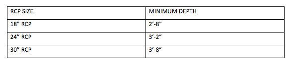
RCP size varies based on depth.Bending Diagram
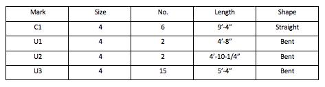
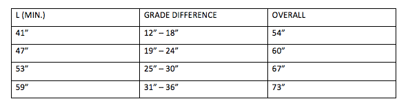
The bending diagram outlines measurements for Bar C (J-hook) at 10” C/C. The long-end length of the bar varies with differential grade (see chart below). The radius of the hook is 2-1/2”, the short end of the bar measures 6”, and the distance between the long end of the bar and the short end of the bar is 5”.Bending Diagram Bars A & BThe #5 deformed reinforced bar has a radius of 2-3/4” (interior) and an exterior radius of 8” or 168 degrees. The length of bar A is 49-1/4” and the length of bar B is 36-1/2”.Section C-CAccording to section C-C details, transitions should be backfilled with sand. Barriers include a ½” expansion joint, #5 bars and a 4” conc. Div. strip (on bridge pier transition only).Detail Expansion JointThe barriers are filled with ¾” pre-molded expansion material. There is a ¾” chamfer on all edges and a 2” clearance (minimum) from reinforcing steel to the nearest face.Section D-DAll vertical stirrup and horizontal reinforcing steel should overlap a minimum of 24” at splices and have a 2” clearance (minimum) from reinforcing steel to the nearest face.There is a grade elevation of 1-1/2” (max.) permissible offset between grade elevations.Des. 1 quantities / ft. are as follows:
  • CONC. (CY) = 0.159
  • STEEL (LBS) = 4.17
Plan of Delineator PlacementDelineators should be placed at 50’-0” centers along the top of median barrier; skew delineators 15 degrees to improve reflectivity.This blog post is an interpretation of specifications by the Oklahoma Department of Transportation. Please consult with Oklahoma DOT's most recent requirements for definitive information.

BUY AND SELL WITH EIFFEL TRADING

Eiffel Trading’s barrier wall inventory is ever-changing, and includes a wide variety of barrier types, including single slope barrier, low profile barrier, jersey barrier, and more. Additionally, our construction equipment inventory ranges from used concrete formwork, to crawler drill rigs, and everything in between.All of our listings are constantly being updated, but if you don’t see what you’re looking for, create a wanted listing for free.Ready to sell your used heavy equipment or construction material? List your products today for free on Eiffel Trading’s online marketplace.If you have any questions or would like additional information, please call us at 1-800-541-7998 or email sales@eiffeltrading.com.
Click to continue

What are Tennessee Bridge Mounted Interconnection Portable Barrier Specifications?

The Tennessee Department of Transportation outlines specifications regarding the proper dimensions for concrete barriers, including general notes, section details, and more.

Tennessee Bridge Mounted Interconnection Portable Barrier General Notes

The Tennessee Department of Transportation’s general instructions are as follows:
  1. Precast concrete barriers should be constructed with Class A concrete manufactured in accordance with Section 604 of the Standard Specifications.
  2. Reinforcing steel should be ASTM A615.
  3. The connector pin should be a 1-1/4” x 25-1/8” F1554 Grade 36 anchor bolt or 1-1/4” x 25-1/8” A307 Grade A bolt. The connector pin, top connector, bottom connector, nuts and washers should be galvanized in accordance with AASHTO M-111. This standard depicts the traditional pin and eye connection details. Any Federal Highway Administration approved, NCHRP 350 compliant connection, such as the J-J hook positive connection, may also be used.
  4. Place all steel reinforcement 2” minimum from the outside face of the barrier, except as otherwise shown.
  5. Payment will be made under item number designated on the plans for bridge mounted interconnected portable barrier rail (per linear foot).
  6. Any salvable value of the portable barrier rail will become the property of the contractor. The portable barrier rail should be moved off the project in a manner and time suitable to the engineer.
  7. When interconnected portable barrier rail is fabricated in the upright position as shown on this drawing, the VB400 lifting bar will become optional and may be omitted from the installation.
  8. This barrier has been successfully tested to the requirements of NCHRP 350. The contractor may submit alternate barriers that have been approved by the Federal Highway Administration as NCHRP 350 compliant. The alternate barriers must be certified by the contractor as having been fabricated in accordance with the approved alternate details.
Different section lengths and different approved connections can be used on a specific project (refer to general notes H and C above). Only one section length and connection type should be used in a single run of interconnected portable barrier rail.
  1. Transverse slots in bottom of rail should be plugged where required to prevent drainage from impinging on traffic lanes, railroad right of way, or as directed by plans.
  2. Immediately after removal of barrier rail, the holes in the bridge deck for the anchor bolts should be cleaned and packed with non-shrink grout. All grouting material should be on the materials and test qualified products list (QLP).

Tennessee Bridge Mounted Interconnection Portable Barrier Specifications

Tennessee barriers should conform to the following specifications, according to the Tennessee Department of Transportation.Plan ViewBarriers include ¾” diameter concrete anchors for mounting vertical panels. Their corners form to a ½” bevel or radius. They measure 2’-3” wide. The distance between the edge of the barrier and the farthest end of the loop bar is 2-1/2” maximum (typical).Barriers include anchor bolt holes that are 2” in diameter. The first anchor bolt hole is spaced 2’-0” from the left end of the barrier; spacing after that depends on the length of the barrier:
  • 2 SPA. @ 4’-3” = 8’-6” (12’-6” Section)
  • 4 SPA. @ 4’-3” = 16’-0” (20’-0” Section)
Elevation ViewEach barrier is 20’-0” long and includes two 6” lifting slots, which are set 3’-4” when measured from the center of the slot to the nearest outer edge of the barrier.On the left side of the barrier, the bottom connector is spaced 6” from the ground level and the upper connector is spaced 6” from the top of the barrier. On the left side of the barrier, the bottom connector is spaced 8” from the ground level and the top connector is spaced 8” from the top of the barrier.Each barrier includes one bar A600, two bars A601, bars A400, bar VB400, bar X600, four bars C400 (on each side), and bars U400.
  • Bar C400 is an L-shaped bar that measures 2’-4” (long end) and 4” (short end)
  • Bar U400 is a U-shaped bar that measures 2’-4-1/2” tall, 1’-8” wide (large end) and 5-1/2” wide (short end)
  • Bar VB400 is a V-shaped bar that measures 10” long on each side and a total of 9” wide for the entire bar
  • Bar X600 is a U-shaped bar that measures 1’-11” (longways) and has a total width of 8”
Lifting Hole and Slot NotesTwo 2” diameter lifting holes are required for each section to be placed 3’-4” from either end of the barrier rail. Additional holes may be added to 20’-0” section lengths. Placement of additional holes to be at the discretion of the fabricator, formed with 2” PVC pipe or equal.Lifting bars are required to prevent spalling of concrete around holes.End ElevationBarriers measure 2’-3” wide on the bottom, 9” wide at the top and stand 2’-8” tall. They include ½” bevel or radius at their top edges and a 10” radius at the break point.Clearance NotesIf 4’-0” of clearance from the toe on the backside of a barrier to the edge of the slab is available then no anchor bolts will be required.Connector PinConnector pins measure 2’-1-1/8” long and include a 1-1/2” threaded end that is fitted with a 1-1/4” heavy hex nut plus a steel washer (F436 typ.). Connector pins are 1-1/4” diameter steel bar F1554 Grade 36.Bottom ConnectorBottom connectors should be galvanized after forming. They are made of ¾” diameter steel bar ASTM A36 and include a 7/8” radius on the closed side. The open side measures a total of 9-1/4” wide.This blog post is an interpretation of specifications by the Tennessee Department of Transportation. Please consult with Tennessee DOT's most recent requirements for definitive information.

BUY AND SELL WITH EIFFEL TRADING

Eiffel Trading’s online marketplace boasts a wide selection of new and used barrier wall, including single slope barrier, k-rail barrier, jersey barrier, and much more. Furthermore, our construction equipment inventory ranges from foundation equipment, to concrete equipment, and everything in between.All of our listings are constantly being updated, but if you don’t see what you’re looking for, create a wanted listing for free.Ready to sell your used heavy equipment or construction material? List your products today for free on Eiffel Trading’s online marketplace.If you have any questions or would like additional information, please call us at 1-800-541-7998 or email sales@eiffeltrading.com.
Click to continue

Sheet Pile Application: Cutoff Wall

A cutoff wall is constructed to keep groundwater out of excavation areas and ultimately to eliminate the need for dewatering using pumping and other methods. Building a cutoff wall typically entails the creation of an impermeable barrier that surrounds the perimeter of the job site. Cutoff walls are most commonly vertical and driven into a deep layer of earth (bedrock or clay) to secure them in place. Sheet pile is a top choice for cut off walls. In addition to being made of sheet piles, cutoff walls may also be made of grout barriers, slurry trench walls, mix-in-place barriers, concrete diaphragm walls, or bored pile walls. Artificial ground freezing may also be used to create a cutoff wall.

MATERIALS

The materials used to construct a cutoff wall depend on both the conditions of the environment in the affected area and the specific needs of a project. Factors like ground conditions, the needed depth of the wall, the needed height of the wall, and whether or not the wall will be a permanent structure all come into play when deciding the proper materials and method.Both steel and plastic sheet piles can be used to construct cutoff walls, but the use of steel is more common. The use of plastic sheet piles is a fairly new development, and plastic is still not considered the most effective and durable option. Both steel and plastic piles used for cutoff walls are ordinarily around 18 inches in width and between 30 to 50 feet in length. Plastic sheet piles should be thick and rigid.

OPERATIONS

Steel sheet pile cutoff walls are a popular choice because they are relatively easy and quick to install and don’t necessitate excavation before their installation. Additionally, they are quite durable. During the construction of a cutoff wall, interlocking steel sheet piles are driven into the ground individually. They are often driven using a vibratory hammer to the required depth. If a greater amount of depth is needed, piles can be welded to those already driven into the ground. In the case of the use of sealable joints, all debris and soil are flushed from joint cavities after which a sealant is added within the cavity.

PROPER CLOSURE

Cutoff walls made of sheet pile sometimes present issues involving leakage through their interlocks. Minimizing the width of openings in interlocks and the insertion of sealant into interlocks can prevent leakage. Additionally, as a cutoff wall is being built, crew members should pay special attention to prevent any damage to sheet piles or interlocks. Neglecting to do so may result in vulnerabilities in the cutoff wall structure that ultimately lead to leakage.Proper closure of sheet piles is integral to the successful build of a cutoff wall. Adequate closure involves control of the inclination of sheet piles on each side of their gap which does not exceed around .2 percent. In order to ensure proper closure and decrease the likelihood of deformation of the cutoff wall, methods such as tack welding and skip welding of the pile may be necessary.In addition to being used for cutoff walls, sheet pile walls are common in a number of different dewatering capacities to form structural walls. For instance, in dam applications, they may be used to prevent horizontal seepage of water through strata that is permeable or semi-permeable.

BUY AND SELL WITH EIFFEL TRADING

Eiffel Trading’s online marketplace inventory ranges widely to include a wide variety of sheet pile, barrier wall, HDPE pipe, and more options. Furthermore, our marine equipment inventory ranges from sectional barges, to winches, to chain pullers, and everything in between.All of our listings are constantly being updated, but if you don’t see what you’re looking for, create a wanted listing for free.Ready to sell your used heavy equipment or construction material? List your products today for free on Eiffel Trading’s online marketplace.If you have any questions or would like additional information, please call us at 1-800-541-7998 or email sales@eiffeltrading.com.
Click to continue

Sheet Pile Application: Culvert Construction

Sheet pile can be used in a couple of different ways as it relates to culvert construction. It can be used to form a culvert side wall in conjunction with a concrete slab as an alternative to the more traditional concrete culvert in channel culvert construction. This is a fairly new and innovative practice, and it’s often simpler and easier than the alternative. It can also reduce the overall costs of construction by reducing project time. Another way sheet pile can be used in culvert construction or culvert replacement is in the building of cofferdam systems.

Culvert Side Wall Construction

A channel culvert is built to secure a channel or waterway during road construction and other construction when the area crosses the water. When sheet pile is applied in the construction of a channel culvert, the following happens:
  • A set of two culvert side walls are spaced separate from each other along the width of the channel or waterway. They are driven into the ground until they reach a hard, secure layer. These side walls are made up of a collection of steel sheet piles.
  • Sheet piles are also connected to the entrance end of the side walls in order to decrease the height of the walls and increase the separation distance between them in order to better drive them into place.
  • A wing wall is installed, which consists of reinforcing steel bars on top of the side walls.
  • A concrete slab is cured and installed in order to produce a culvert plate.
The end result of this process eliminates the need for the construction of a typical concrete culvert, which takes longer to set into place and is thus more expensive to build. Additionally, because the sheet pile side walls are driven deep into the ground, the culvert is structurally strong, which reduces the likelihood of cracking or deformation. This ultimately reduces the need for maintenance and lowers maintenance costs in the long run.

Sheet Pile in Culvert Replacement

Sheet pile is often used in cofferdam construction as a part of culvert replacement and construction projects. Cofferdams are typically made up sandbags, sheet piles, or an inflatable structure. Sandbags may be the most budget-friendly option, but they are not effective in areas where water rises above six feet or so. In such a case, sheet piles are the best choice. In the case of needing excavation beyond 2 feet in order to embed a sizeable culvert, sheet piles are driven deep into the ground to block channel flow.When a cofferdam is constructed using sheet pile, the following occurs:
  • The sheet piles are driven in pairs across the water to obstruct its flow.
  • Piles are driven into the substrate next to the shoreline to properly seal off the flow of water from the project site.
  • The length of the sheet piles used for a particular project varies based on factors like soil conditions and the type of rocks in the area.
  • The sheet piles need to be driven far enough to block flow while also having enough height to adequately act as a protective barrier for the work area.
  • Sheet piles are most often driven into the ground using a vibratory hammer.
  • On occasion, small sandbags are placed around the periphery of the sheet pile in order to further fortify the area and prevent water flow.

Overall

Overall, sheet piles can play an important role in culvert construction and replacement. In the case of side wall construction, the use of sheet piles can make channel culvert construction easier and lower the costs of the project. And in the case of cofferdam construction for culvert projects, sheet piles are the best solution for areas involving water depths that exceed 6 feet or for projects that require excavation that exceeds 2 feet.

BUY AND SELL WITH EIFFEL TRADING

Eiffel Trading’s construction material inventory ranges from new and used sheet pile, to used HDPE pipe, to new and used steel plates, and much more. Furthermore, we have a wide selection of marine equipment including winches, sectional barges, and more.All of our listings are constantly being updated, but if you don’t see what you’re looking for, create a wanted listing for free.Ready to sell your used heavy equipment or construction material? List your products today for free on Eiffel Trading’s online marketplace.If you have any questions or would like additional information, please call us at 1-800-541-7998 or email sales@eiffeltrading.com.
Click to continue

What are the New Mexico Temporary Precast Concrete Wall Barrier Anchoring Details?

The New Mexico Department of Transportation outlines specifications regarding the proper dimensions for temporary concrete wall barrier anchors, including general notes and anchoring methods.

New Mexico Temporary Precast Concrete Wall Barrier Anchoring Details General Notes

The New Mexico Department of Transportation’s general instructions are as follows:
  1. Anchors should be used when specified in the plans and when a clear area of 5 feet behind the temporary concrete wall barrier cannot be maintained.
  2. Each 10 foot section of barrier required 2 anchor assemblies when installed on concrete, and 4 anchor assemblies when installed on asphalt or soil.
  3. Expansion anchors will not be permitted for use on bridge decks.
  4. Do not drill holes into prestressed concrete bridge deck panels.
  5. Use ASTM A325 high strength galvanized anchor bolts.
  6. Drill anchor holes in concrete with a pneumatic drill.
  7. For barrier sections that extend across concrete joints, do not anchor on both sides of the joint. Omit the anchor closest to the joint.
  8. Tighten anchors to a “snug fit.” Turn threaded rods at least 1 full turn of threads extending above the nut. Do not protrude the top of the anchor above the side of the barrier.
  9. Coat anchors with the adhesive bonding anchoring system with a debonding agent so the anchors can be easily removed. Do not reduce the strength or anchors system with the debonding agent.
  10. Once removed, completely fill anchor holes with an approved non-shrink, non-metallic grout, or as directed by the project manager.

New Mexico Temporary Precast Concrete Wall Barrier Anchoring Methods

Concrete barrier anchors in New Mexico should include the following features, according to the New Mexico Department of Transportation specifications.Thru-Deck Anchor MethodNote that this method is only to be used on bridge decks and only at times when specified in the plans, or when directed by the engineer.The thru-deck anchor method includes the following features:A heavy hex nut at the top paired with a barrier washer that’s set 5-1/8” from the bridge deck surface. The inner end of the washer extends 5-1/2” from the outer end of the barrier. The washer is ½” thick (high). The nut and washer connect to a 7/8” diameter doubled ended threaded rod, which is inserted into a 1” minimum diameter hole (which is drilled into the bridge deck).Deck washers include a central 1” diameter hole. They measure ½” thick, 6-1/8” long and 6-1/8” wide.Adhesive Bonding System Anchor MethodThis method is used for bridge decks and portland cement concrete pavements.The adhesive bonding system anchor method includes the following features:A 7/8” diameter anchor bolt paired with a barrier washer, which is set 5-1/8” from the bridge deck surface. Within the barrier, the bolt is set inside a 1-1/2” x 2” slotted adjustment hole thru barrier. In the bridge deck slab or portland cement concrete pavement, the anchor hole is drilled “normal.” Anchor is installed by adhesive bonding system. The anchor embedment depth should be recommended by the manufacturer.Barrier Washer DimensionsExcluding deck washers, general barrier washers measure 3-1/4” x 4” and are ½” thick. They included a 1” diameter hole centered on the washer.Anchor Bolt MethodNote that these embedment depths are typical for most applications. However, due to varying soil and asphalt conditions, they may not be adequate for all cases.The anchor bolt method system is used for bituminous pavements and soil and includes the following features:A 7/8” diameter anchor bolt paired with a barrier washer, which is set 5-1/8” from the ground surface. An anchor hole is drilled or driven into the pavement or soil.Minimum embedment:
  • 1’-8” for asphalt pavements greater than 1’-6”
  • 2’-0” for asphalt pavements less than 1’-6”
  • 2’-6” for soil
This blog post is an interpretation of specifications by the New Mexico Department of Transportation. Please consult with New Mexico DOT's most recent requirements for definitive information.

BUY AND SELL WITH EIFFEL TRADING

Eiffel Trading’s online marketplace advertises a wide variety of new, surplus, and used barrier wall types, including f-shape barrier, single slope barrier, and much more. Furthermore, our construction equipment inventory ranges from foundation equipment, to concrete equipment (including concrete formwork!) and much more.All of our listings are constantly being updated, but if you don’t see what you’re looking for, create a wanted listing for free.Ready to sell your used heavy equipment or construction material? List your products today for free on Eiffel Trading’s online marketplace.If you have any questions or would like additional information, please call us at 1-800-541-7998 or email sales@eiffeltrading.com.
Click to continue

What are the New Mexico Temporary Precast Concrete Wall Barrier Specifications?

The New Mexico Department of Transportation outlines specifications regarding the proper dimensions for temporary concrete wall barriers, including general notes, plan view details, elevation details and section details.

New Mexico Temporary Precast Concrete Wall Barrier General Notes

The New Mexico Department of Transportation’s general instructions are as follows:
  1. All work should be in accordance with the New Mexico Department of Transportation’s Standard Specifications for Highway and Bridge Construction, Current Edition.
  2. All devices seeking department approval should conform to the following:
a. Follow the approval process defined by the Department.b. Conform to NCHRP report 350 for crashworthiness.
  1. Concrete should be Class A concrete in accordance with Section 510 of the New Mexico State Department Standard Specifications for Highway and Bridge Construction, Current Edition.
  2. Shop drawings should be submitted prior to fabrication.
  3. The contractor should not intermix the use of concrete wall barrier designs of type 32, type 42 and temporary concrete wall barriers shown on sheet 4 of 5 of their set of standard drawings.
  4. Mandatory: 1” x 12” lifting coil with double flared loops (safe working load of 8,000 lbs.)
  5. Placement of concrete wall barriers should extend a minimum of 60 feet beyond the area of concern unless wall barriers are anchored.
  6. In order to allow for the deflection of concrete wall barriers, a clear area of at least 5 feet must be maintained behind the barrier unless anchorage is used.
  7. Consecutive lengths of temporary concrete wall barriers should always be connected by utilizing the connecting pin assembly shown on 606-20-2/5.

New Mexico Temporary Precast Concrete Wall Barrier Specifications

Concrete barriers in New Mexico should include the following features, according to the New Mexico Department of Transportation specifications.Elevation ViewBarriers include two drainage slots, which are set 3’-4” apart from each other (when measured from their centers). The left drainage slot sits 3’-4” from the left edge of the barrier, and the right drainage slot sits 3’-4” from the right end of the barrier (when measured from their centers).There are three connection loop bars protruding from each end of the barrier (for a total of six loops in all). On the left side of the barrier, the loops are spaced as follows:
  • Distance from bottom of the barrier to the lower loop: 8”
  • Distance from the lower loop to the middle loop: 1’-2”
  • Distance from the middle loop to the highest loop: 4”
  • Distance from the highest loop to the top of the panel: 6”
On the right side of the barrier, the loops are spaced as follows:
  • Distance from bottom of the barrier to the lower loop: 6”
  • Distance from the lower loop to the middle loop: 4”
  • Distance from the middle loop to the highest loop: 1’-2”
  • Distance from the highest loop to the top of the panel: 8”
Loop bars measure ¾” in diameter.Each barrier includes both #6 deformed bars and #3 bar cages.Centered on the barrier is a 1” x 12” double lifting coil (see general note #6).Plan ViewBarriers measure 10’-0” long and 2’-0” high. They include a 1” typical taper at the traffic approach corners. All loops are projected 2” (typ.) from the end of the barrier.Loop DetailsWhen two barriers come together through the use of the loop bars, there should be a maximum gap of 2-1/4” between them and a minimum gap of 1-1/4”, which is created by the taper at the end of the barrier.

New Mexico Temporary Precast Concrete Wall Barrier Section Details

Concrete barrier sections in New Mexico should include the following features, according to the New Mexico Department of Transportation specifications.Section A-ABarrier widths measure 2’-0” on the bottom and 6” at the top. The v-notch measures 1’-0” wide. The vertical reveal measures 3” high. Each barrier includes a top loop bar, a 1-1/4” diameter steel bar (Grade 36), and a bottom loop bar, as well as a ¾” chamfer or radius.Section B-BSection B-B shows that each barrier includes ¾” diameter smooth loop bars (top), a #6 deformed bar, ¾” diameter smooth loops bars (bottom), and an anchoring slot.Section C-CSection C-C shows that each barrier includes slotted holes on either side of the barrier. Note that triangular space in the base of a barrier is typical, though a circular arch shape will be permitted.This blog post is an interpretation of specifications by the New Mexico Department of Transportation. Please consult with New Mexico DOT's most recent requirements for definitive information.

BUY AND SELL WITH EIFFEL TRADING

The Eiffel Trading marketplace allows contractors to sell their unwanted assets, including various barrier wall types such as k-rail barrier, single slope barrier, low profile barrier, and more. Furthermore, our marine equipment inventory ranges from work boats, to sectional barges, and much more.All of our listings are constantly being updated, but if you don’t see what you’re looking for, create a wanted listing for free.Ready to sell your used heavy equipment or construction material? List your products today for free on Eiffel Trading’s online marketplace.If you have any questions or would like additional information, please call us at 1-800-541-7998 or email sales@eiffeltrading.com.
Click to continue

What are Montana Concrete Barrier Rail Specifications?

The Montana Department of Transportation outlines specifications regarding the proper dimensions for concrete barrier rails, including general notes, plan view details, elevation details, section details and loop fabrication requirements.

Montana Concrete Barrier Rail General Notes

The Montana Department of Transportation’s general instructions are as follows:
  1. Use class deck concrete or equivalent.
  2. Reinforcing steel consists of deformed bars conforming to AASHTO M 31 Grade 60.
  3. Connect each 10” section with connecting pins as details and conforming to AASHTO M 270, Grade 36 or better. Connecting pins need not be painted.
  4. Cutouts on edges of each section are shown with slight taper to facilitate form removal. Rectangular cutouts are acceptable.
  5. The contractor is responsible for the proper fit up of the precast concrete barrier rail. Assemble and pin sufficient number of precast sections in the fabrications plant to determine that proper fit up can be maintained on all roadway alignment curves as well as on tangent. This is to be determined early in the fabrication.
  6. Attach reflectors to the rail every 30’. Use aluminum alloy meeting the aluminum association alloy AA5052-H32. Follow the manufacturer’s specifications for adhesive mounting. In narrow pave median applications, reflectorize both sides.
  7. Do not install unanchored concrete barrier rail for obstacles within 6.5’ of the base (traffic side) of the rail.
  8. The optional tapered end shown in an acceptable alternate to the vertical end for all concrete barrier rail ends.
  9. Galvanize or epoxy coat loops and connecting pins after fabrication/bending. Galvanize in accordance with ASTM A153, B695 (Class 50) or other applicable ASTM galvanizing standards.

Montana Concrete Barrier Rail Loop Fabrication Requirements

Loop fabrications in Montana should conform to the following specifications according to the Montana Department of Transportation:Requirements
  1. Use reinforcing steel conforming to ASTM A 706, Grade 60 for rebar being welded to loops.
  2. Loop ends consist of smooth round bars conforming to AASHTO M 270, Grade 36.
  3. Cold bend the loops by using a jog that will produce an accurate radius without marring the bar. Do not heat the bar to facilitate bending.
  4. Weld rebar to loops meeting section 624 requirements using 1/8” diameter E8018 rod. Do not tack weld the pieces together prior to welding.
  5. No additional welding is permitted on the smooth round bars r reinforcing steel.
Optional Loop Details
  1. Use continuous smooth round bars conforming to AASHTO M 270, Grade 36 to fabricate the optional loops.
  2. Cold bend the loops by using a jig that will produce an accurate radius without marring the bar. Do not heat the bar to facilitate bending.
  3. No welding is permitted on the smooth round bars or reinforcing steel.

Montana Concrete Barrier Rail Specifications

Concrete barrier rails in Montana should include the following features, according to the Montana Department of Transportation specifications.Elevation ViewBarriers should include a reflector and may have an optional tapered end. Barriers also have a lifting slot that is 3’-10” in length.On the left hand side of the barrier, the top loop is spaced 9-7/8” from the top of the barrier; the middle loop is spaced 7-1/2” from the top lop; and the bottom loop is spaced 7-1/2” from the middle loop.On the right hand side of the barrier, the top loop is spaced 8-1/8” from the top of the barrier; the middle loop is spaced 7-1/2” from the top lop; and the bottom loop is spaced 7-1/2” from the middle loop.Plan ViewBarriers include 16 #5s (typ.) spaces spaced 7” apart, with a 4” gap on either side.End ViewA barrier break point occurs 1’-1” from the ground line. There is a 10” R at the break point and a 1” R at the vertical reveal. The Upper slope should measure 5” wide from the center of the barrier and the bottom slope should measure 7” wide from the center of the barrier.This blog post is an interpretation of specifications by the Montana Department of Transportation. Please consult with Montana DOT's most recent requirements for definitive information.

BUY AND SELL WITH EIFFEL TRADING

Eiffel Trading’s precast barrier rail inventory is ever-changing, and includes various types of barrier wall including low profile barrier, k-rail barrier, single slope barrier, and much more. Furthermore, our construction material inventory ranges from used crane mats, to new and used steel plates, and more.All of our listings are constantly being updated, but if you don’t see what you’re looking for, create a wanted listing for free.Ready to sell your used heavy equipment or construction material? List your products today for free on Eiffel Trading’s online marketplace.If you have any questions or would like additional information, please call us at 1-800-541-7998 or email sales@eiffeltrading.com.
Click to continue

What are the North Dakota Concrete Barrier Specifications?

The North Dakota Department of Transportation outlines specifications regarding the proper dimensions for concrete barriers, including general notes, plan view details, elevation details, end view details and connection details.

North Dakota Concrete Barrier General Notes

The North Dakota Department of Transportation’s general instructions are as follows:
  1. Galvanize all exposed hardware as per ASTM A153, except for the loop inserts.
  2. Use AAE-3 Concrete.
  3. Provide steel in accordance with Section 612 of NDDOT Standard Specifications.
  4. Imprint barrier ends A and B as shown with 4-inch letters. Field match A end with B end.
  5. Place barrier markers at the center of the barrier at 20’ centers.
  6. Connect barrier sections with 1-1/4” diameter A-307 double hex connecting bolt. Maintain bottom nut and washer connection for duration of barrier installation.
  7. Place barrier to minimize openings between individual sections.

North Dakota Concrete Barrier Specifications

North Dakota barriers should conform to the following specifications according to the North Dakota Department of Transportation:Side ViewBarriers should measure 10’ long and 32” high. They include two lifting slots, which are each 8” long and 2” high. The left lifting slot is set 30” from the left end of the barrier (when measured from the center of the slot), and the right lifting slot is set 30” from the right end of the barrier (when measured from the center of the slot). Each barrier includes as U1 and U2 on the left and right sides, with a height of 17-3/4” between each U1 and U2.Plan ViewAccording to the plan view and in reference to U3, there are “14 spaces at 8” each.”End ViewBarriers are 30” wide on the bottom and 12” wide at the top. They measure 32 high. There is a 3” vertical reveal, and the break point occurs 13” from the ground line. The height of the bottom slope is 10” and the height of the upper slope is 19”. A 10” Rad is optional.North Dakota Concrete Barrier DetailsNorth Dakota barriers should conform to the following specifications according to the North Dakota Department of Transportation:Barrier Marker DetailsUse the same color reflective faces as the edge line along barrier edges.Bar ListReflective TapeUse retroreflective, acrylic microprism material with acrylic backing, 3" wide, providing the following minimum optical performance with an observation angle of 0.1' measured in candlepower for the reflector:AdhesiveUse factory applied solid butyl rubber that’s 1/8” thick, 2” wide on 2-1/4” wide release paper on surface 3 to temporarily mount markers to portable concrete barrier.Marker BodyUse high impact, weatherable engineering thermo-plastic material conforming to the following:Bolt Connection DetailsBolt connections include a double hex connection bolt that’s 1-1/4” in diameter, and a nut and washer with a 3/8” minimum thickness. Bolts should measure 25” long and include a 3” threaded end.

Buy and Sell with Eiffel Trading

Eiffel Trading’s online marketplace boasts a wide variety of barrier wall types for sale, including f-shape barrier, single slope barrier, k-rail barrier, and much more. Additionally, our construction material inventory also ranges to include used crane mats, used steel pipe, etc.All of our listings are constantly being updated, but if you don’t see what you’re looking for, create a wanted listing for free.Ready to sell your used heavy equipment or construction material? List your products today for free on Eiffel Trading’s online marketplace.If you have any questions or would like additional information, please call us at 1-800-541-7998 or email sales@eiffeltrading.com.
Click to continue

What are Nebraska Concrete Barrier Wall Specifications?

The Nebraska Department of Transportation outlines specifications regarding the proper fabrication, installation and setup of concrete protective barriers.

Nebraska Concrete Barrier General Notes: Fabrication and Installation

The Nebraska Department of Transportation’s general instructions are as follows. Note that these details are for the fabrication and installation of concrete protection barriers, and the details described are typical.
  1. Concrete protection barriers should be made of 5,000 PSI concrete and be precast in accordance with applicable portions of Section 705 in the standard specifications. The forms may be removed when the concrete has attained a compressive strength of 2,175 PSI. The barriers may be transported within the plant once the concrete has attained a compressive strength of 3,000 PSI. The barriers may be shipped when the concrete has attained a compressive strength of 5,000 PSI.
  2. Reinforcing steel used within the concrete should conform to the requirements of ASTM A 615, Grade 60.
  3. The loop reinforcing steel should be smooth, meeting the requirements of ASTM A 706, Grade 60 or ASTM A 615, Grade 60, which has been modified to meet the following physical and chemical requirement:
a. Tensile Requirementsi. Yield strength: 60,000 PSI minimumii. Tensile strength: 80,000 PSI minimumiii. Elongation in 8-inch: 14% minimumb. Chemical composition (max percents)i. Carbon: 0.30ii. Manganese: 1.50iii. Phosphorus: 0.035iv. Sulfur: 0.045v. Silicon: 0.50The loop should pass a 180 degree bend test on a 2-3/4” pin.
  1. The Contractor or supplier should furnish the materials. They should research the manufacturer’s certified test reports for the actual heat of the steel being used that shows the chemical and physical test results for the loop reinforcing steel. This should be done before coating or fabrication begins.
  2. All steel should be zinc-coated as specified below, or epoxy coated to Nebraska standards.
  3. Zinc-coated (galvanized) steel bars should meet the requirements of ASTM A 123, (coating Grade 100, minimum coating of 2.30 ounces per square foot). The bars should be fabricated prior to galvanizing. The procedures of ASTM A 143 should be observed as applicable. All zinc coating damage due to fabrication or handling should be repaired with a zinc dust formulation in accordance with ASTM A 780.
  4. The coating plant intending to supply the loop reinforcing steel should notify the Materials and Research Division two to three weeks before processing any material in order to arrange for NDOT personnel to inspect the materials. This should be done during the coating and fabrication process.
  5. The contractor should provide the engineer a letter certifying the concrete protection barriers for use on this project have been made in accordance with these plans.

Nebraska Concrete Barrier General Notes: On Site Response

The Nebraska Department of Transportation’s general instructions for onsite response processes are as follows:
  1. Concrete protection barriers are the property of the contractor.
  2. The contractor should provide for an approved monitoring schedule, with a person on call and available 24 hours a day, each day of the week, to realign concrete protection barriers that have been struck.
  3. Initiation of this service should be within one hour of notification of need.

Nebraska Concrete Barrier General Notes: Specifications

The Nebraska Department of Transportation’s general instructions for barrier specifications are as follows:
  1. Use 1-1/8” diameter ASTM A 307 anchor bolts with heavy hex nut and washer (A36). Use ASTM A36 non-coated steel for the connection pin.
  2. In regards to surface preparation, when place on a paved surface, all loose dirt and sand should be removed from the roadway prior to placement of the barrier.
  3. Barriers must be pulled tight during installation to remove slack.
  4. At no time should be barriers be lifted by use of the loop bars.
This blog post is an interpretation of specifications by the Nebraska Department of Transportation. Please consult with Nebraska DOT's most recent requirements for definitive information.

BUY AND SELL WITH EIFFEL TRADING

The Eiffel Trading marketplace allows contractors to sell their unwanted assets, including various barrier wall types such as f-shape barrier, single slope barrier, k-rail barrier, and more. Furthermore, our marine equipment inventory ranges from used sectional barges, to used push boats, and much more.All of our listings are constantly being updated, but if you don’t see what you’re looking for, create a wanted listing for free.Ready to sell your used heavy equipment or construction material? List your products today for free on Eiffel Trading’s online marketplace.If you have any questions or would like additional information, please call us at 1-800-541-7998 or email sales@eiffeltrading.com.
Click to continue

What are the Nebraska Concrete Protection Barrier Specifications?

The Nebraska Department of Transportation outlines specifications regarding the proper dimensions and requirements of concrete protective barriers in their state.

Nebraska Concrete Barrier Elevation, Plan and End View Specifications

The Nebraska Department of Transportation elevation view, plan view and end view specifications are as follows.

Elevation View

Barriers includes four lifting slots, each measuring 1’-0” in length. The leftmost lifting slot begins 2’-1-1/2” from the left end of the barrier, and the rightmost lifting slot begins 2’-8” from the right end of the barrier.Each barrier includes three loop bars that protrude from the left and right side of the barrier. These loops bars are labeled 6D1, 6D2 and 6D3. The loop bars should be spaced as follows:
  • Distance between 6D1 and 6D2 on the left side: 3”
  • Distance between 6D2 and 6D3 on the left side: 7-1/2”
  • Distance between 6D1 and 6D2 on the right side: 3”
  • Distance between 6D2 and 6D3 on the right side: 1’-5”
Each barrier includes anchor bolt blockout on both sides, which is located at the center of the barrier.Plan ViewEach barrier measures 12’-6” long and 1’-10-1/2” wide.End ViewBarriers measure 1’-10-1/2” at the bottom and 8” at the top. Barriers measure 2’-8” tall and include two anchor bolt blockouts, one on each side. Each barrier includes a 3” vertical reveal. There are 7” from the top of the reveal to the break point (10” from the groundline to the breakpoint). The height of the bottom slope is 7”, and the height of the upper slope is 1’-10”. The width of the bottom slope is 5”, and the width of the upper slope is 2-1/4”.

Nebraska Concrete Barrier Loop Bar and Anchor Bolt Details

The Nebraska Department of Transportation loop bar and anchor bolt specifications are as follows.Anchor Bolt Blockout DetailsAnchor bolts should be placed on the traffic side only when shown in the plans.Anchor bolts are inserted into a hole that is 2” in diameter. The bolt is 1-1/8” in diameter A307 anchor bolt with heavy hex nut. When installed, the hex nut should sit 4” above the ground line. Each bolt should be outfitted with a square washer that measures ½” x 3” x 3”.Loop Bar DetailsLoop bars have a diameter of 2-3/4” (on the curved end) and measure 4-1/4” wide, when observing from an elevation view. According to the Nebraska Department of Transportation, “dimensions are out to out of bars unless otherwise noted.”This blog post is an interpretation of specifications by the Nebraska Department of Transportation. Please consult with Nebraska DOT's most recent requirements for definitive information.

BUY AND SELL WITH EIFFEL TRADINGS

Eiffel Trading is a one-stop-shop for all of your new, used, and surplus temporary barrier wall needs! Our inventory is ever-changing, and ranges from k-rail barrier wall, to low pro barrier wall, and everything in between, including various DOT approved options. Furthermore, our construction material options include used crane mats, new and used HDPE pipe, used steel pipe, and much more.All of our listings are constantly being updated, but if you don’t see what you’re looking for, create a wanted listing for free.Ready to sell your used heavy equipment or construction material? List your products today for free on Eiffel Trading’s online marketplace.If you have any questions or would like additional information, please call us at 1-800-541-7998 or email sales@eiffeltrading.com.
Click to continue
Previous page Next page

© 2025 Eiffel Trading, LLC. All Rights Reserved. Terms of Services / Privacy Policy