What are Texas Single Slope Concrete Barrier (Precast) X-Bolt Connection, Restrained, Mash TL-4 Specifications?
The Texas Department of Transportation outlines specifications regarding the dimensions of single slope concrete barriers (precast, X-bolt connection, restrained, MASH TL-4), including elevation view notes, plan view details, section details, and more.
Texas Single Slope Concrete Barrier (Precast) X-Bolt Connection, Restrained, Mash TL-4 Specifications
Elevation View
Barriers measure 30’-0” long and include a 1” end cover (typ.) on both ends. Barriers also include two leave-out blocks on each side (for a total of four blocks per panel). Within the barrier is a WWR cage (A), WWR cage B, U1 (#4) bars, and DB (#8) bars.
The WWR cage (A) includes 21 bars spaced 1’-2” apart for a total of 24’-6” of cage length. The WWR cage (B) also includes 21 bars spaced 1’-2” apart for a total of 24’-6” of cage length.
Barriers include an expansion joint that measures 12” (minimum), and are set over a bridge slab or continuously reinforced concrete pavement (CRCP) that is at least 7” thick.
Plan View
Barrier plan views show an X-bolt connection made of PVC pipe that is 1-1/2” in circumference (Sch 40). The bolts are angled at 70 degrees, and the adjacent precast barrier segments are connected at their symmetrical center with a joint connection.
View A-A
Barriers stand 3’-6” tall and measure 8” wide at the top and 24” wide at the bottom. They include a ¾” chamfer (typ.) on all corners. The barrier slope is 8” wide (on each side). Barriers are symmetrical down the center line in dimensions, though their interior reinforcing bars are not symmetrical. Barriers are set atop bridge slabs or CRCP that’s at least 7” thick. Beneath this slab, it’s permissible to have a slab edge or breakback edge for phased construction. There is a minimum distance of 1-1/2” (typ). between all interior reinforcing bars and the outside edge of the barrier.
It should be noted that threaded rods with nuts and washers for X-bolt connections are not included in view A-A for clarity.
Top and Bottom Threaded Rod Assembly Details
Top threaded rods measure 2’-8” long and are 7/8” in diameter. They are fully threaded rods (ASTM A193 Gr B7 or F1554 Gr 105). Top threaded rods include a PL washer that is ½” x 4” x 4” (ASTM A361) with a 1” diameter hole in the center. Washers are 7/8” hardened steel (ASTM F436).
Bottom threaded rods measure 3’-6” long and are 7/8” in diameter. They are fully threaded rods (ASTM A193 Gr B7 or F1554 Gr 105). Bottom threaded rods include a PL washer that is ½” x 4” x 4” (ASTM A361) with a 1” diameter hole in the center. Washers are 7/8” hardened steel (ASTM F436).
Installation of threaded rods must not extend beyond the face of the barrier.
Leave Out Block Details
View B-B:
View B-B shows a 1-1/2” PVC sleeve (Sch 40) that is set to the left of the leave-out block. The leave-out block measures 1’-3” long and 5-3/8” tall. The PVC sleeve is centered vertically next to the leave-out block.
Top View:
A top view shows that the PVC sleeve is set on the opposite of the face side of the barrier.
X-Bolt Connection with Forming and Leave-Out Block Placement Details
The leave-out block on the left side (the left barrier segment) is set 11-1/8” from the joint connection. The leave-out block on the right side (the right barrier segment) is set 1’-3-7/8” from the joint connection. The left-hand leave-out blocks are spaced 1’-5” from the ground line, and the right-hand leave-out blocks are spaced 2’-2” from the ground line.
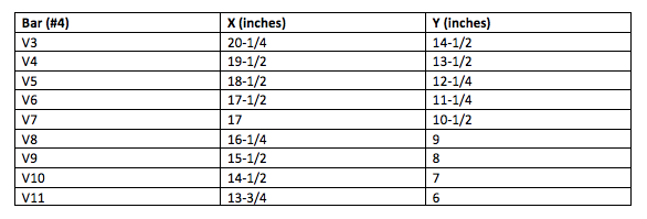
Bar Details
Bars BD (#8) measure 1’-5-1/2” long.
Bars U1 (#4) are U-shaped bars that measure 3’-6” long and 11-3/4” wide (from open end to open end).
Bars U2 (#4) are U-shaped bars that measure 3’-6” long and 8-1/4” wide (from open end to open end).
Welded Wire WWR Details
Cage A measures 5’-1/2” wide at the top and 1’-8-1/4” wide at the bottom. It stands 3’-3” tall.
Cage B measure 5-1/4” wide at the top and 7” wide at the bottom. It stands 1’-7” tall.
This blog post is an interpretation of specifications by the Texas Department of Transportation (TxDOT). Please consult with TxDOT' most recent requirements for definitive information.

BUY AND SELL WITH EIFFEL TRADING
Eiffel Trading’s online marketplace allows contractors to buy and sell materials and equipment, including various types of used precast barrier wall. Our barrier wall inventory ranges from DOT spec, to single slope, to low profile, and everything in between. Furthermore, our foundation equipment inventory includes pile drivers, vibratory hammers, and much more.
All of our listings are constantly being updated, but if you don’t see what you’re looking for, create a wanted listing for free.
Ready to sell your used heavy equipment or construction material? List your products today for free on Eiffel Trading’s online marketplace.
If you have any questions or would like additional information, please call us at 1-800-541-7998 or email sales@eiffeltrading.com.